Countersink Drawing Callout
Countersink Drawing Callout - Web extracted to 2d drawings. These include countersink and counterbore holes, which allow the use of various types of screws in the mounting holes of the board. By matthew jourden brighton high school brighton, mi. Web a countersink consists of a conical hole that is coaxial to a cylindrical hole, where the angle of the cone is determined by the fastener to be used. The purpose of a countersink is to allow a fastener, typically a flathead screw, to sit slightly below the surface of. The radius is simply indicated as r or full r. Counterbored holes are specified by giving the diameter of the drill, the diameter of the counterbore, and the depth of the counterbore. Calling out a countersink in a drawing requires the 3 dimensions to be called out along with the appropriate gd&t symbols. You can edit the hole note after the hole feature is created: Web a countersink hole is one in which the outer edge of the hole has been opened up to a conical entry. Check the add a note check box to create the hole note. Calling out countersink drawings accurately is crucial for successful manufacturing and engineering processes. This handout will focus on the standards of annotation for fasteners, and hole callouts (local notes). In the graphics window, select the note. In the quiz that completes the activity, they associate these symbols with. Draw the line radially, so that it points toward the center of the hole, and if extended it would pass through the center point. Web countersink callouts:when creating technical drawings or specifications, countersink holes can be indicated using callouts that provide specific details such as the angle, depth, and diameter of the countersink. You can specify precision, select an. In. Web a countersink consists of a conical hole that is coaxial to a cylindrical hole, where the angle of the cone is determined by the fastener to be used. Web countersink and counterbore. Is this hole going into a flat surface? This handout will focus on the standards of annotation for fasteners, and hole callouts (local notes). Use the format. Draw the line radially, so that it points toward the center of the hole, and if extended it would pass through the center point. These callouts help ensure consistency and accuracy during manufacturing and assembly processes. These include countersink and counterbore holes, which allow the use of various types of screws in the mounting holes of the board. Web these. Description of a countersink and counterbore hole and how to dimension them in an autodesk. If the specification of the manufacturing processes Design a 6 x 4 x 1.5 block. Many of these elements are notational in nature. Edit the callout in the dimension propertymanager. In the graphics window, select the note. In the model tree, expand the hole feature, and select the note. Description of a countersink and counterbore hole and how to dimension them in an autodesk. This tutorial is designed to show how to create a counterbore hole in two different ways. I don't have access to someone who knows and i. Web extracted to 2d drawings. A lot of altium designer tools are aimed at solving them. Some older blueprints may use the notation csk to identify a countersink dimension. In the model tree, expand the hole feature, and select the note. Web the callout is as follows: This tutorial is designed to show how to create a counterbore hole in two different ways. A lot of altium designer tools are aimed at solving them. In the quiz that completes the activity, they associate these symbols with machining applications. 1.1 symbols permit consistency in the way dimensions and tolerances are specified, and each symbol has a clearly defined. The radius is simply indicated as r or full r. You can edit the hole note after the hole feature is created: Write the number of holes. Web extracted to 2d drawings. Draw the line radially, so that it points toward the center of the hole, and if extended it would pass through the center point. A lot of altium designer tools are aimed at solving them. Calling out a countersink in a drawing requires the 3 dimensions to be called out along with the appropriate gd&t symbols. Check the add a note check box to create the hole note. Calling out countersink drawings accurately is crucial for successful manufacturing and engineering processes. Write the number. Edit the callout in the dimension propertymanager. Counterbored holes are specified by giving the diameter of the drill, the diameter of the counterbore, and the depth of the counterbore. Description of a countersink and counterbore hole and how to dimension them in an autodesk. An arc length is dimensioned using the arc length symbol. Ergonomics and convenience are important issues when designing a printed circuit board and the device as a whole. For a symmetric part, it is only necessary to dimension to one side of the center line of symmetry. If the specification of the manufacturing processes A lot of altium designer tools are aimed at solving them. These include countersink and counterbore holes, which allow the use of various types of screws in the mounting holes of the board. Web these callouts use standard symbols for number of places, diameter, depth, counterbore, and countersink. The radius is simply indicated as r or full r. Web extracted to 2d drawings. I need to call out a countersunk hole in a sheet metal panel. Web countersink and counterbore. Calling out a countersink in a drawing requires the 3 dimensions to be called out along with the appropriate gd&t symbols. Countersinks allow a screwhead to sit slightly below the surface of a part to prevent exposed screwheads on that surface.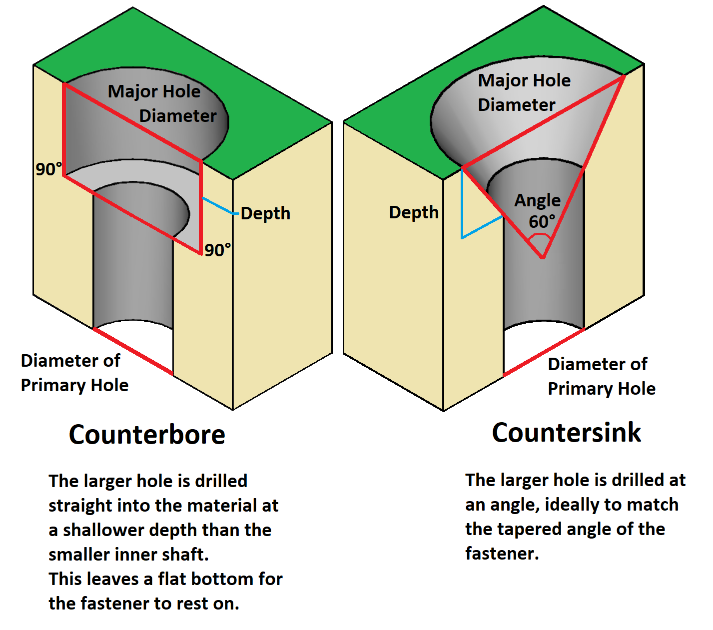
PCB Hole Types Counterbore vs Countersink ABL Circuits
Countersink Example3 OER
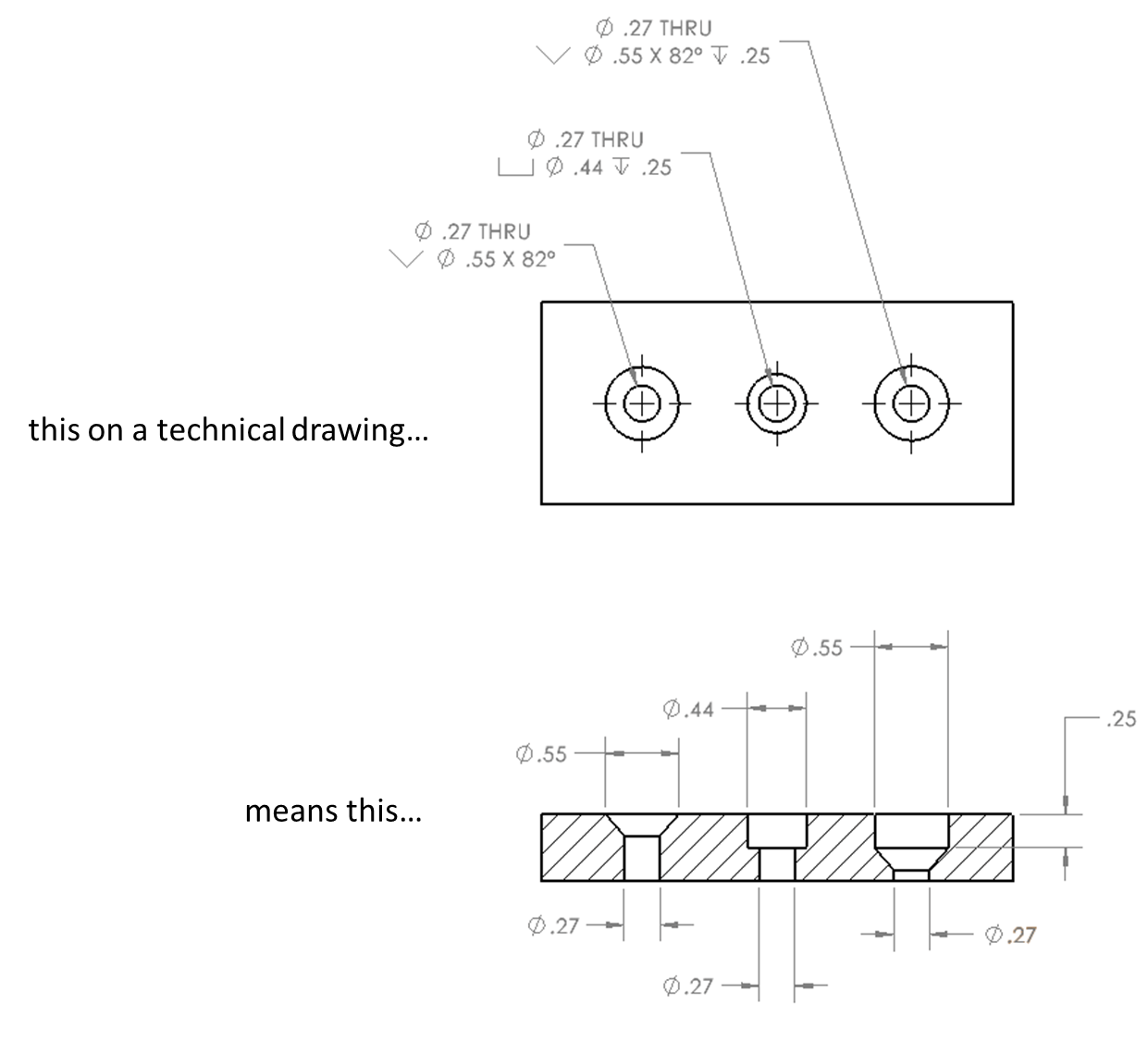
The Benefits of Countersinking SendCutSend
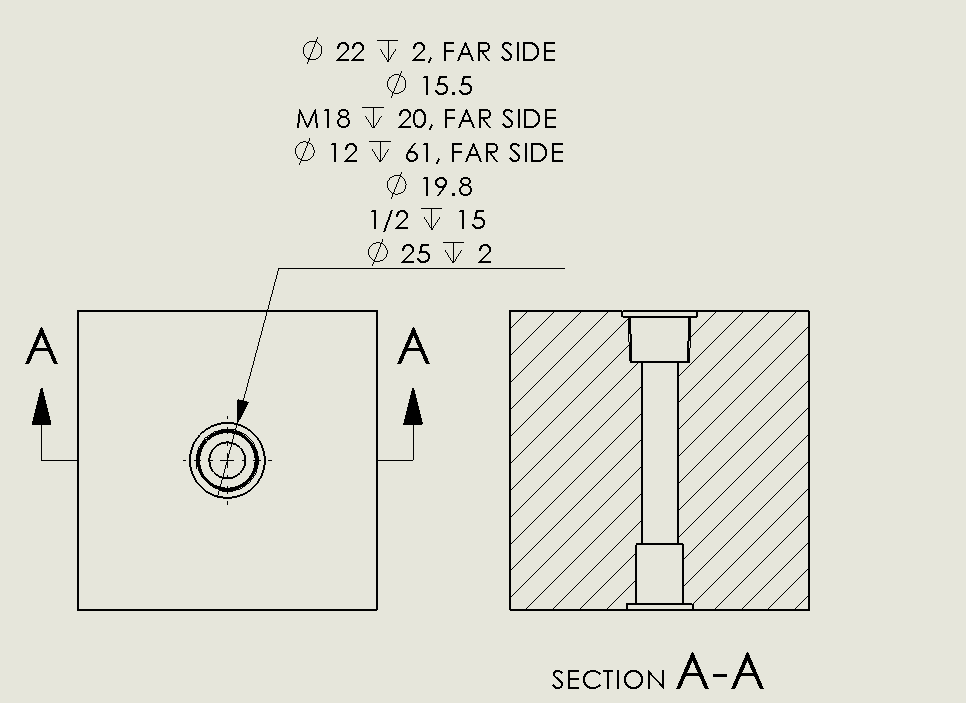
SOLIDWORKS 2018 Advanced Hole & Callout Tutorial Innova Systems
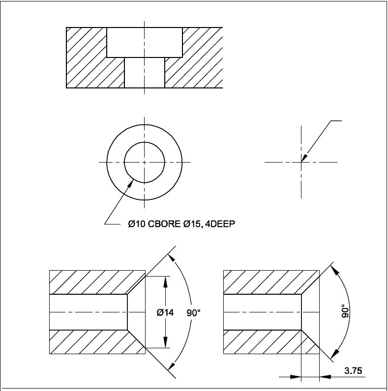
ENGINEERING DRAWING Dimensioning

PLTW IED 5.5 Countersink in Fusion 360 YouTube
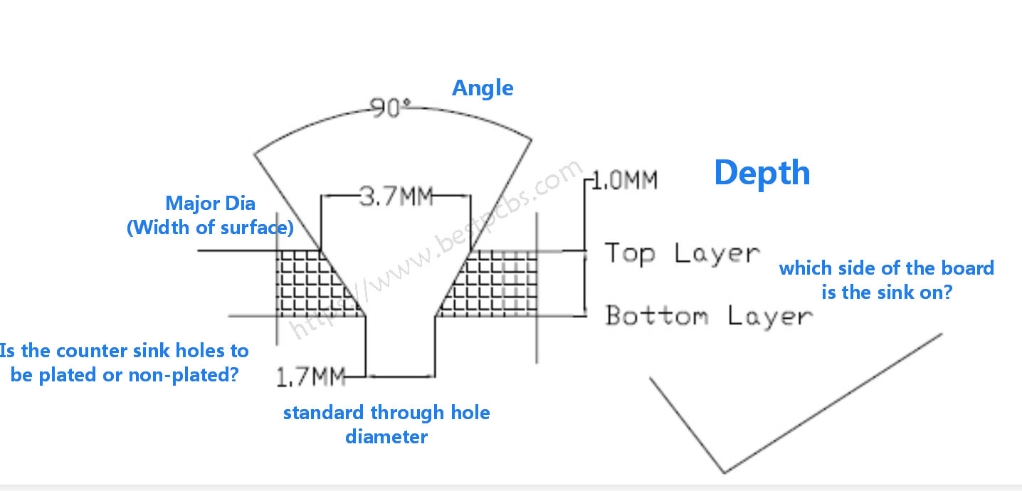
What’s the Countersink and counter bore on a PCB drawing?

PPT Chapter 10 cont. PowerPoint Presentation, free download ID1984589
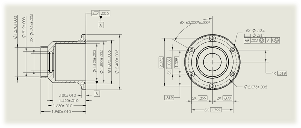
Tips and Tricks for Defining and Organizing Hole Callouts in SOLIDWORKS
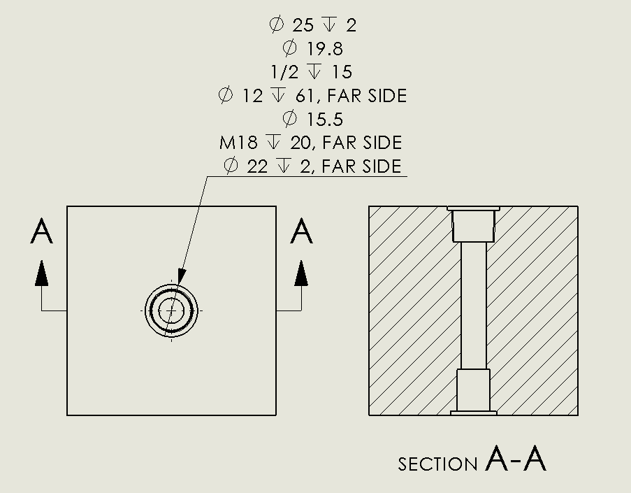
SOLIDWORKS 2018 Advanced Hole & Callout Tutorial Innova Systems
Learners Examine The Drawing Symbols Used For Counterbore, Countersink, Spotface, Radius, Diameter, And Depth.
If You Want To Type The ⌵ Symbol, Hold The Alt Key And Press 9013.
These Callouts Help Ensure Consistency And Accuracy During Manufacturing And Assembly Processes.
Annotation Standardization Is Provided By The Asme
Related Post: