Drawing Moment Diagrams
Drawing Moment Diagrams - Web shear and moment diagrams are graphs which show the internal shear and bending moment plotted along the length of the beam. 90k views 3 years ago statics. This example deals with a constant distributed force (shear is a linear function of x). 🟦 18.2 relationships between load, shear, and moment. In this diagram, the horizontal axis (x) typically represents the length of the beam and the vertical axis (y) represents the magnitude and direction of the bending moment. Welcome to our free beam calculator! Web a bending moment diagram provides a graphical representation of how bending moment changes along the length of a beam. So in this post we’ll give you a thorough introduction to shear forces, bending moments and how to draw shear and moment diagrams. They allow us to see where the maximum loads occur so that we can optimize the design to prevent failures and reduce the overall weight and cost of the structure. 591 views 3 years ago united states. We go through breaking a beam into segments, and then we learn. Learn to draw shear force and moment diagrams using 2 methods, step by step. Web shear and moment diagrams. Web this can be done by creating a shear and bending moment diagram. This is an example problem that will show you how to graphically draw a shear and. Web this can be done by creating a shear and bending moment diagram. The moment diagram will plot out the internal bending moment within a horizontal beam that is subjected to multiple forces and moments perpendicular to the length of the beam. This page will walk you through what shear forces and bending moments are, why they are useful, the. Below is a simple example of what shear and moment diagrams look like, afterwards, the relation between the load on the beam and the diagrams will be discussed. There is a long way and a quick way to do them. In this diagram, the horizontal axis (x) typically represents the length of the beam and the vertical axis (y) represents. Simply model your beam using the calculator, and hit solve. Web calculate bending moment diagrams. The steps to create the bending moment diagram for a beam are listed below. It is an essential tool for engineers and designers to analyze structures and ensure they can withstand applied forces. Web this can be done by creating a shear and bending moment. Web a bending moment diagram is a graphical representation of the bending moments experienced by a beam under load along the beam length. We go through breaking a beam into segments, and then we learn. There is a long way and a quick way to do them. The moment diagram will plot out the internal bending moment within a horizontal. 90k views 3 years ago statics. Web a bending moment diagram is a graphical representation of the bending moments experienced by a beam under load along the beam length. In this diagram, the horizontal axis (x) typically represents the length of the beam and the vertical axis (y) represents the magnitude and direction of the bending moment. If you’re not. The steps to create the bending moment diagram for a beam are listed below. Welcome to our free beam calculator! If you’re not in the mood for reading,. There is a long way and a quick way to do them. It is an essential tool for engineers and designers to analyze structures and ensure they can withstand applied forces. Engineers use these diagrams to analyze beams and ensure that they can effectively support the applied loads. 291k views 2 years ago engineering statics. Web shear and moment diagrams. Web steps to construct shear force and bending moment diagrams. Our calculator generates the reactions, shear force diagrams (sfd), bending moment diagrams (bmd), deflection, and stress of a cantilever beam or. 🟦 18.2 relationships between load, shear, and moment. 🟦 18.3 principles of graphical integration. The steps to create the bending moment diagram for a beam are listed below. 90k views 3 years ago statics. Web a bending moment diagram is a graphical representation of the bending moments experienced by a beam under load along the beam length. Web steps to construct shear force and bending moment diagrams. Our calculator generates the reactions, shear force diagrams (sfd), bending moment diagrams (bmd), deflection, and stress of a cantilever beam or simply supported beam. Web under our paid version of skyciv beam the calculator will show you the full hand calculations and the steps taken to hand calculate your bending. Web a bending moment diagram provides a graphical representation of how bending moment changes along the length of a beam. Web shear and moment diagrams are graphs which show the internal shear and bending moment plotted along the length of the beam. Web the first step in calculating these quantities and their spatial variation consists of constructing shear and bending moment diagrams, \(v(x)\) and \(m(x)\), which are the internal shearing forces and bending moments induced in. Our calculator generates the reactions, shear force diagrams (sfd), bending moment diagrams (bmd), deflection, and stress of a cantilever beam or simply supported beam. Draw a free body diagram of the beam with global coordinates (x) calculate the reaction forces using equilibrium equations ( ∑ forces = 0 and ∑ moments = 0 ) cut beam to reveal internal forces and moments*. Welcome to our free beam calculator! Web moment diagrams are similar to shear diagrams, use them to find the location and value of the maximum positive and negative moment, or the moment at any specific location. Simply model your beam using the calculator, and hit solve. Determine new origin (x n) and use positive sign conventions to label. This section will discuss three related but different methods to produce shear and bending moment diagrams, and conclude with a comparison of the advantages and. So in this post we’ll give you a thorough introduction to shear forces, bending moments and how to draw shear and moment diagrams. Web calculate bending moment diagrams. This page will walk you through what shear forces and bending moments are, why they are useful, the procedure for drawing the diagrams and some other keys aspects as well. 🟦 18.2 relationships between load, shear, and moment. This is an example problem that will show you how to graphically draw a shear and moment diagram for a beam. We go through breaking a beam into segments, and then we learn.
Learn How To Draw Shear Force And Bending Moment Diagrams Engineering

Moment Diagrams Constructed by the Method of Superposition
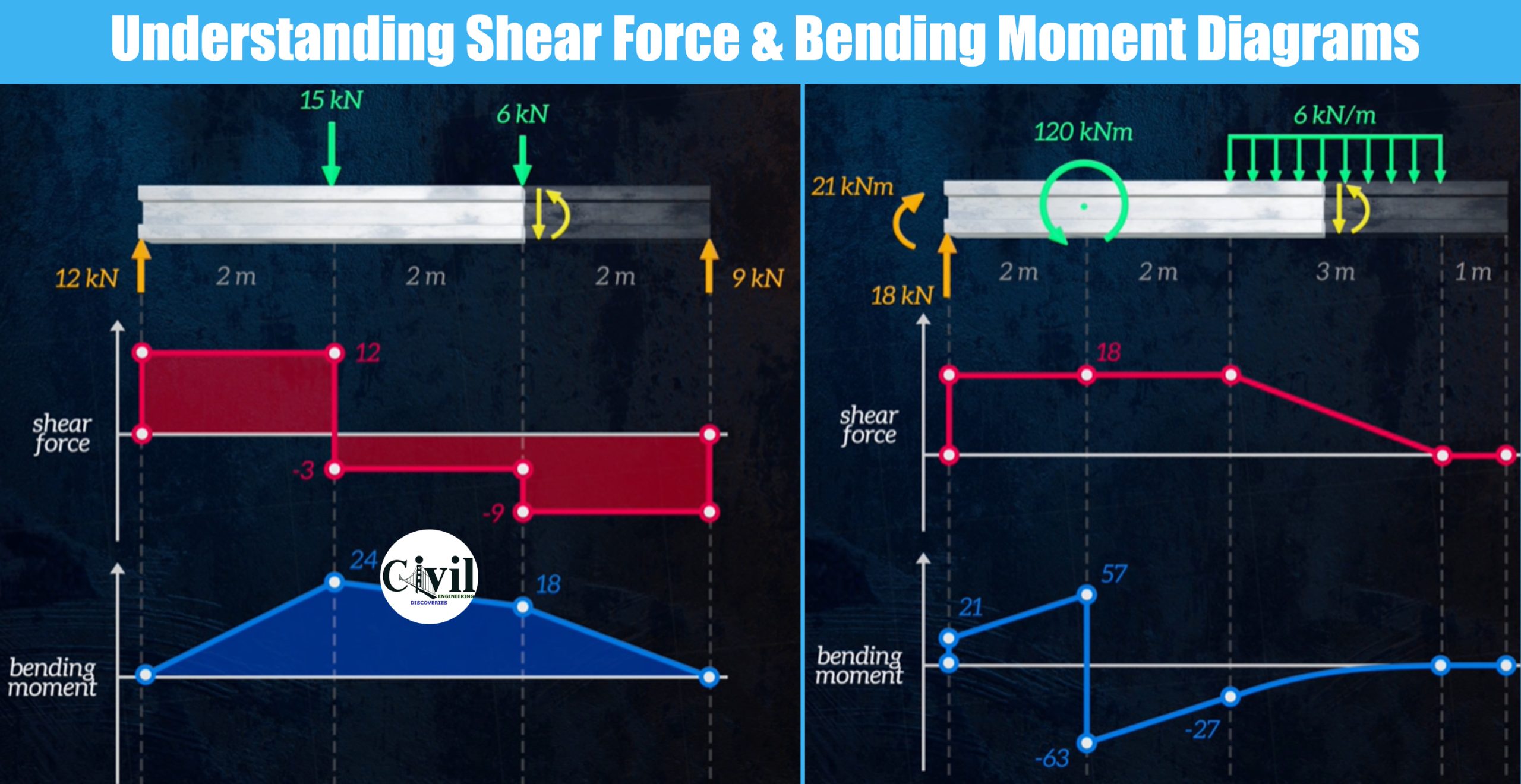
Understanding Shear Force And Bending Moment Diagrams Engineering
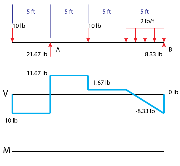
» How to Draw Moment Diagrams ReviewCivilPE
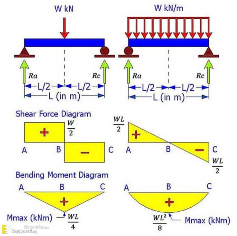
Brief Information About Shear Force And Bending Moment Diagrams

Learn How To Draw Shear Force And Bending Moment Diagrams Engineering

How to draw shear and moment diagrams YouTube
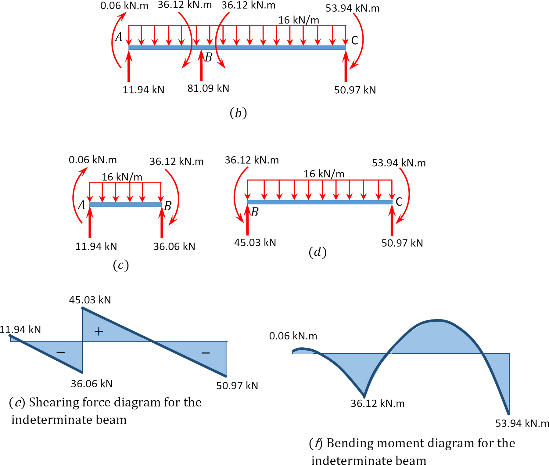
Moment Diagram By Parts
Shear and moment diagrams geekloki
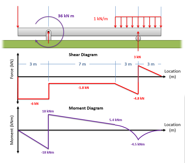
Mechanics Map Shear and Moment Diagrams
Web A Bending Moment Diagram Is A Graphical Representation Of The Bending Moments Experienced By A Beam Under Load Along The Beam Length.
In This Diagram, The Horizontal Axis (X) Typically Represents The Length Of The Beam And The Vertical Axis (Y) Represents The Magnitude And Direction Of The Bending Moment.
This Example Deals With A Constant Distributed Force (Shear Is A Linear Function Of X).
Web Under Our Paid Version Of Skyciv Beam The Calculator Will Show You The Full Hand Calculations And The Steps Taken To Hand Calculate Your Bending Moment Diagrams.
Related Post: