Example Engineering Drawing
Example Engineering Drawing - When a very small object such as components of a wristwatch, is enlarged in some regular proportion to accommodate its drawing. Introduction to engineering drawings (iso) watch on. Blue = center line of piece or opening; This is a complete guide to the types of holes found in machining. Web we’ll start by explaining what an engineering drawing is. Web 3.1 geometric shapes and their significance. Furthermore, we showed you how the usual detailed and assembly drawing looks like. Civil engineering drawings are the bedrock of any construction project, acting as the visual roadmap that guides engineers, architects, and construction teams toward successful project completion. Magenta = phantom line or cutting plane line We can observe engineering drawings as a unified language that engineers use to communicate independently of each other’s spoken or written language. What the difference is between counterbore and countersink holes. Civil engineering drawings are the bedrock of any construction project, acting as the visual roadmap that guides engineers, architects, and construction teams toward successful project completion. Magenta = phantom line or cutting plane line Web we’ll start by explaining what an engineering drawing is. We’ll look at the different parts of. Engineering graphics is an effective way of communicating technical ideas and it is an essential tool in engineering design where most of the design process is graphically based. This is a complete guide to the types of holes found in machining. When a very small object such as components of a wristwatch, is enlarged in some regular proportion to accommodate. How each type of hole is used in engineering. Methods of making engineering drawing. Web understanding the types, principles, and significance of engineering drawing views empowers engineers and designers to communicate design intent effectively, visualize complex geometries accurately, and ensure manufacturability and compliance with industry standards. Here is an example of an engineering drawing (an isometric view of the same. It is more than simply a drawing, it is a graphical language that communicates ideas and information. Engineering drawing is what most of us have learnt during the preliminary years of engineering — isometric drawings to. This textbook makes engineering drawing fun and easy to understand. How each type of hole is used in engineering. Drawings and pictures are among. “drawing” usually means using drawing instruments, from compasses to computers to bring precision to the drawings. Orthographic projection, isometric projection, and assembly drawings. There are few researches particularly focusing on the extraction of information from engineering drawing tables. By understanding the purpose and conventions of each type,. Web figure 1 shows example of engineering drawing. Web the purpose of this guide is to give you the basics of engineering sketching and drawing. Web understanding the types, principles, and significance of engineering drawing views empowers engineers and designers to communicate design intent effectively, visualize complex geometries accurately, and ensure manufacturability and compliance with industry standards. Here is an example of an engineering drawing (an isometric view. Drawings and pictures are among the best means of communicating one’s ideas and views. What the difference is between counterbore and countersink holes. Web engineering working drawings basics. There are few researches particularly focusing on the extraction of information from engineering drawing tables. This textbook makes engineering drawing fun and easy to understand. We will treat “sketching” and “drawing” as one. We’ll also talk about different kinds of engineering drawings. Magenta = phantom line or cutting plane line Engineering drawings use standardised language and symbols. Have you ever visited an automotive dealership, a mattress store, or a window business? Web the rules for creating engineering drawings (communication) are defined by a standards organization (for example, iso and asme). An engineering drawing is a subcategory of technical drawings. Magenta = phantom line or cutting plane line Engineering drawings use standardised language and symbols. The symbols used for each hole and how they are shown on engineering drawings. Engineering drawings use standardised language and symbols. An engineering drawing is a subcategory of technical drawings. Web table of contents. Web explore the three primary types of engineering drawings: Now we will dig deeper into the basic elements of engineering drawings and explain each of them in more detail. Web we’ll start by explaining what an engineering drawing is. Web figure 1 shows example of engineering drawing. We will treat “sketching” and “drawing” as one. An engineering drawing is a subcategory of technical drawings. The different line types are colored for clarity. A 30 mm radius plain disc is represented on the drawing by a circle of 30 mm radius. “sketching” generally means freehand drawing. This textbook makes engineering drawing fun and easy to understand. Web engineering drawing is the foundation for clearly communicating design ideas through visuals. Engineering graphics is an effective way of communicating technical ideas and it is an essential tool in engineering design where most of the design process is graphically based. Web explore the three primary types of engineering drawings: The purpose is to convey all the information necessary for manufacturing a product or a part. What the difference is between counterbore and countersink holes. This is just an introduction. Understanding the basics of engineering drawing is a great first step. It uses technical drawings and diagrams to express the construction and operation of mechanical and structural concepts.
How to prepare a technical drawing for CNC machining 3D Hubs

Mechanical Engineer Drawing at GetDrawings Free download
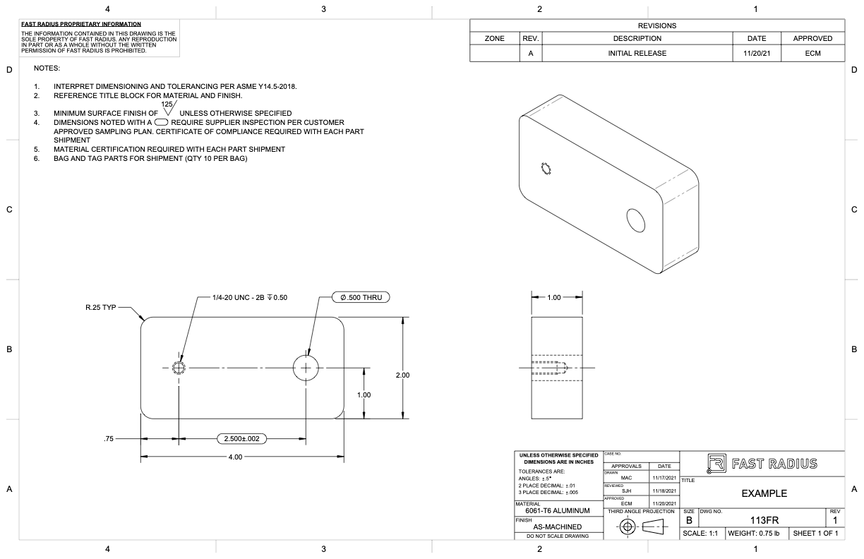
What to Include in Your Engineering Drawing Fast Radius
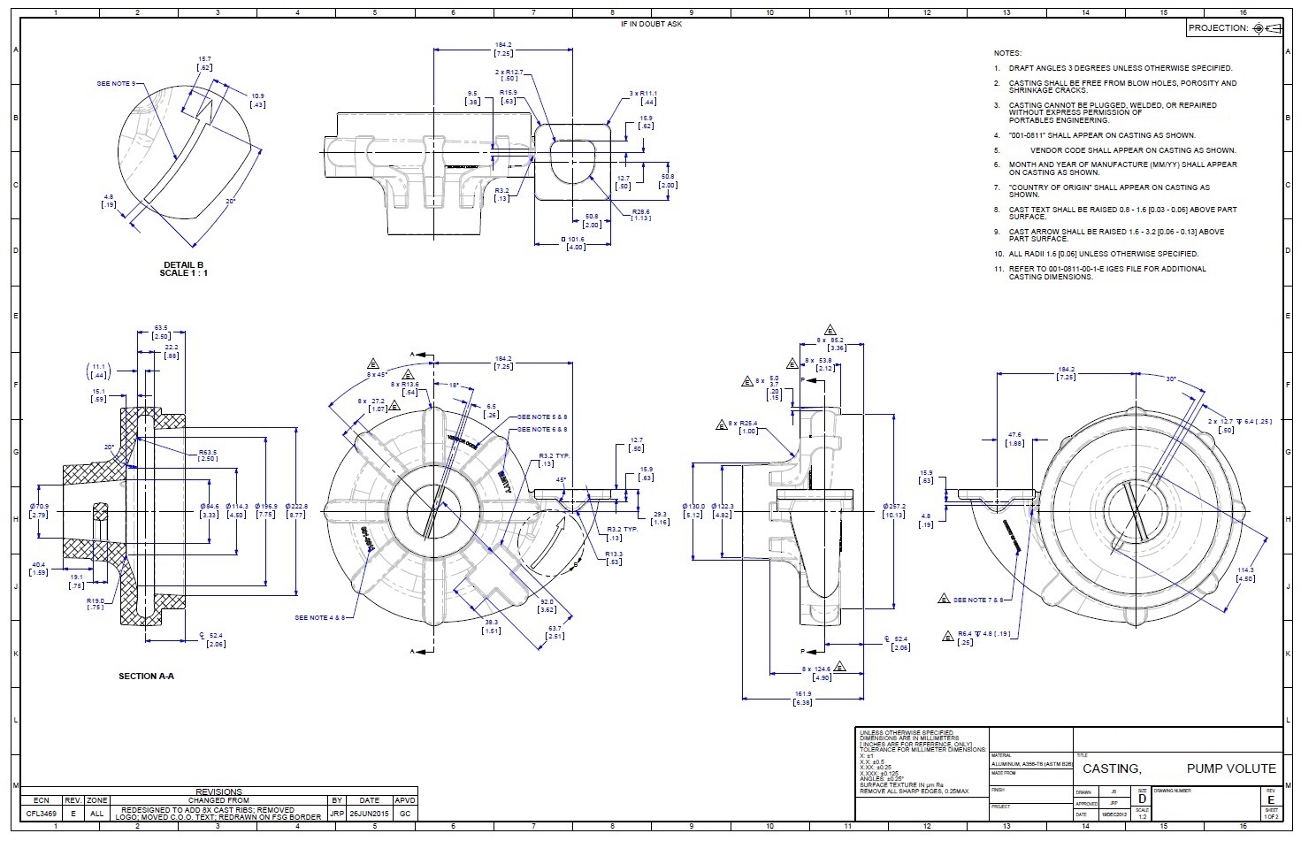
Engineering Drawings Justin R. Palmer

Mechanical Engineering Drawing and Design, Everything You Need To Know

Lecture Notes Engineering Drawing Part 5
tutorial 15 3D Engineering Drawing 2 (AUTO CAD.. ) GrabCAD Tutorials
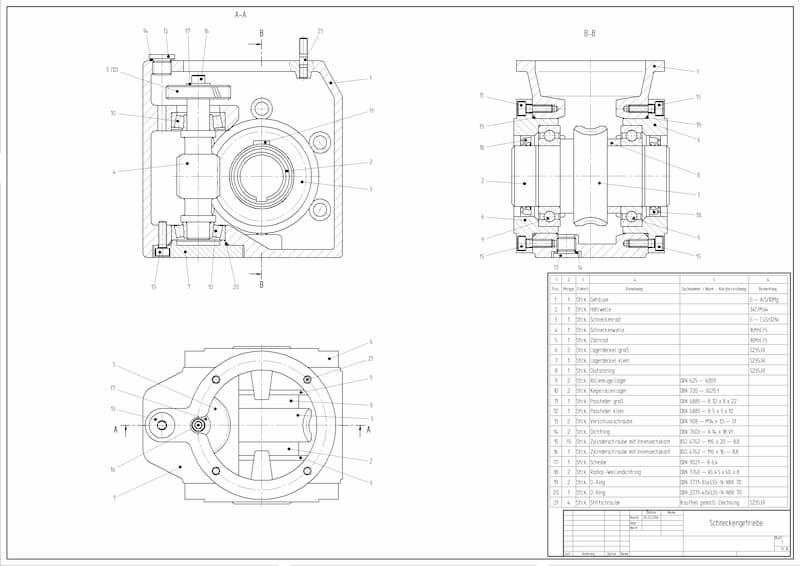
Engineering Drawing Views & Basics Explained Fractory
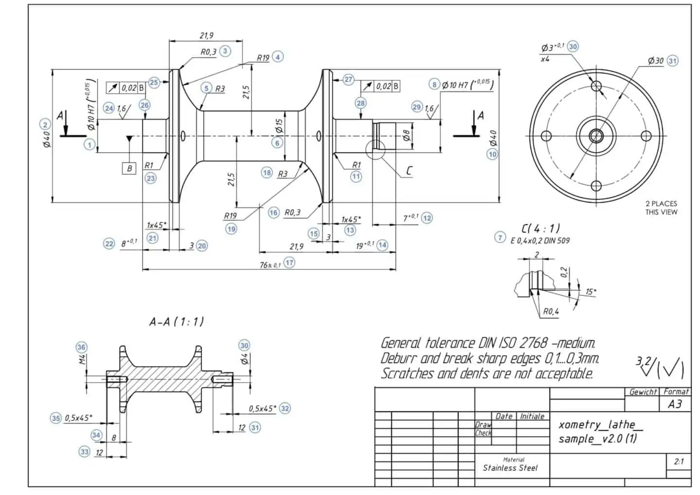
How To Prepare A Perfect Technical Drawing Xometry Europe
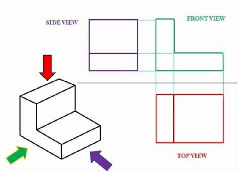
Engineering Drawing Views & Basics Explained Fractory
It Is More Than Simply A Drawing, It Is A Graphical Language That Communicates Ideas And Information.
Web Engineering Drawings, Also Known As Mechanical Drawings, Manufacturing Blueprints, Drawings, Etc., Are Technical Drawings That Show The Shape, Structure, Dimensions, Tolerances, Accuracy, And Other Requirements Of A Part In The Form Of A Plan.
Orthographic Projection, Isometric Projection, And Assembly Drawings.
So I’ve Prepared A Sample Set Of Our Structural Engineering House Plans For Your Enquiring Mind!
Related Post:
