Technical Drawing Isometric
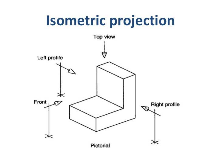
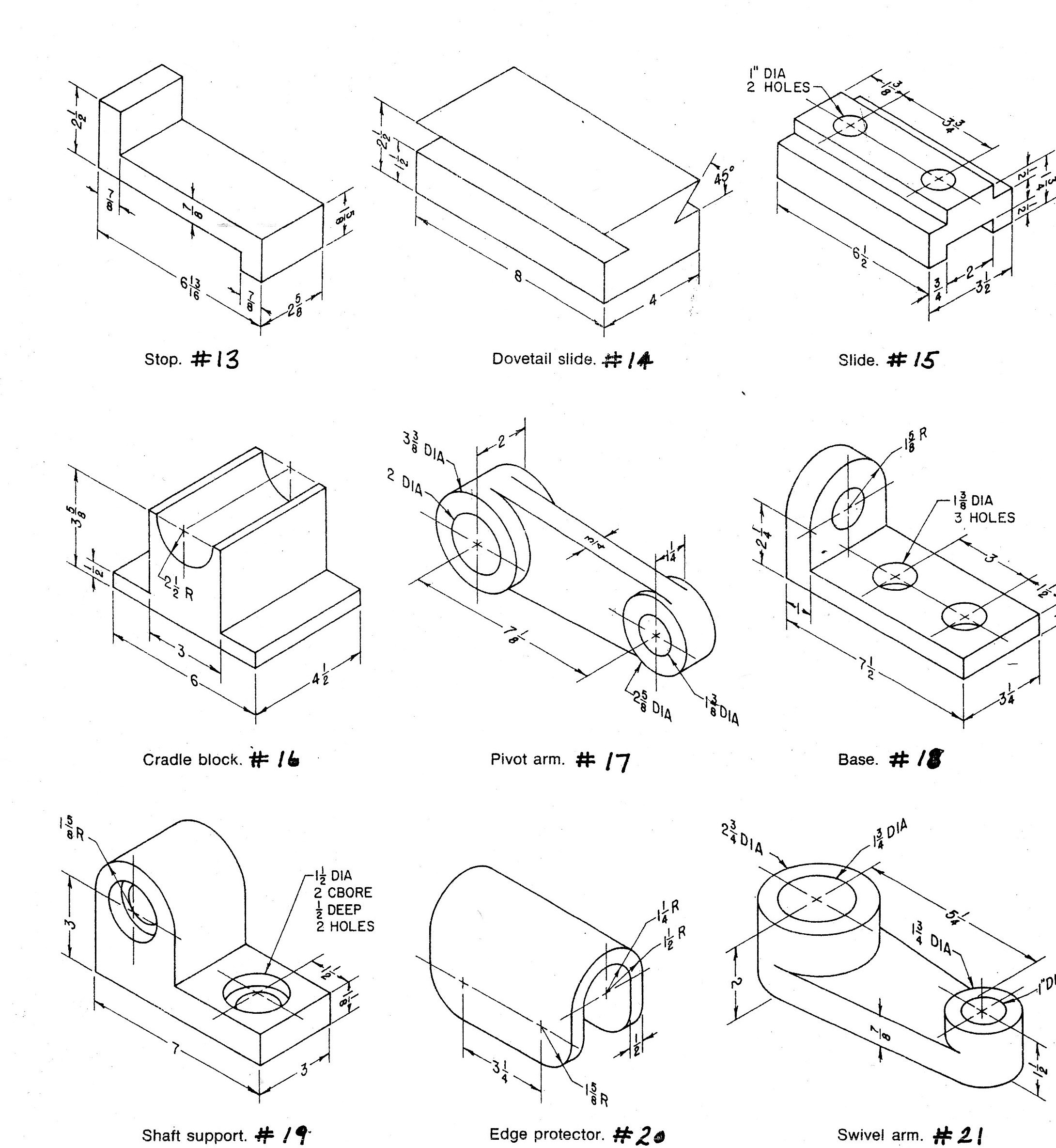
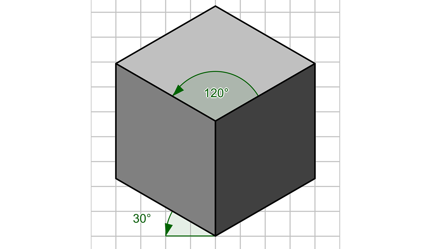
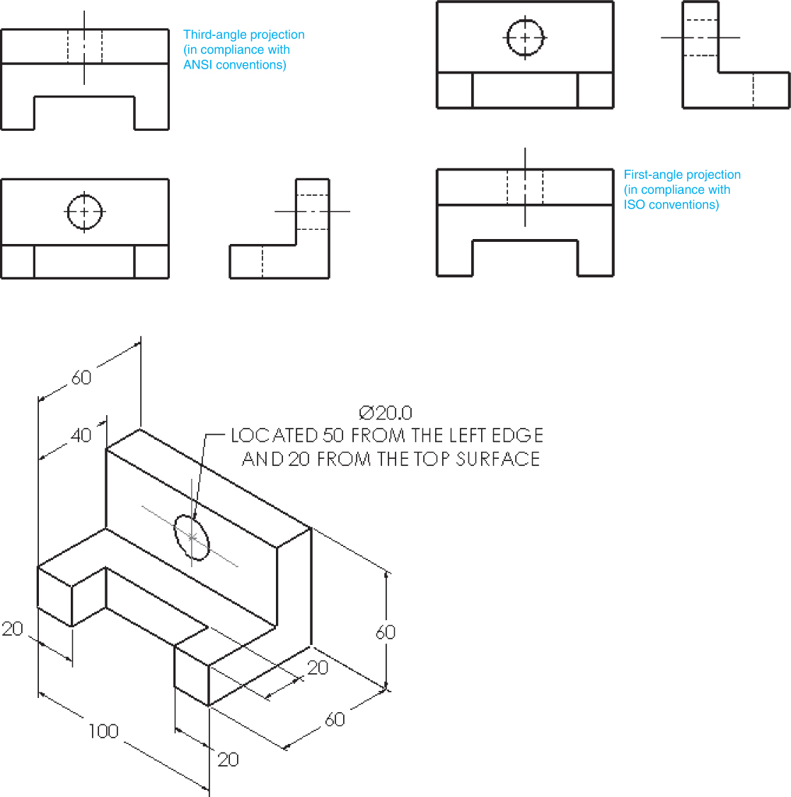
Technical Drawing Isometric - These drawings are particularly useful for conveying a clear understanding of how different parts of a structure fit together. Web an isometric drawing is a pictorial representation of an object in which all three dimensions are drawn at full scale. When drawn under these guidelines, the lines parallel to these three axes are at their true (scale) lengths. Web identify views used in technical drawings including perspective, isometric, oblique, orthographic, plans, elevations, and sections. Learn to draw isometric projections using these simple steps provided. It uses a set of three equal angles to depict the object's height, width, and depth without distortion. Web 89k views 3 years ago isometric projection for beginners. The technique is intended to combine the illusion of depth, as in a perspective rendering, with the undistorted presentation of the object’s principal dimensions. Create a single template that can be used for detail and assembly drawings compliant with asme or iso standards (depending on location). The drawing axes of the isometrics intersect at an angle of 60°. Learn how to get started with isometric design in illustrator by creating some simple objects on an isometric grid that demonstrate technical illustration techniques. It looks like an isometric projection. Web in an isometric drawing, the object’s vertical lines are drawn vertically, and the horizontal lines in the width and depth planes are shown at 30 degrees to the horizontal.. It uses a set of three equal angles to depict the object's height, width, and depth without distortion. Christophe dang ngoc chan, mike horvath) isometric drawings are a good way to show measurements and how components fit together, and is used in technical drawing, often by engineers and architects. Web these best practices apply to 2d drafting and creating technical. It is a type of 3d drawing that uses a 3d representation, but the angles between the axes are always 120 degrees and the proportions are maintained, giving the illusion of depth and space. When drawn under these guidelines, the lines parallel to these three axes are at their true (scale) lengths. Web an isometric drawing is a pictorial representation. Web for a specific user the creation of an isometric drawing in an autocad plant 3d collaboration project is very slowly, while it is fast for other users, creating the same isometric drawing of the same project. This technique is based on using the plan, elevation and profile views of an object to obtain an isometric representation, which means that. The technique is intended to combine the illusion of depth, as in a perspective rendering, with the undistorted presentation of the object’s principal dimensions. Web a piping isometric drawing is a technical drawing that depicts a pipe spool or a complete pipeline using an isometric representation. Distances measured along an isometric axis are correct to scale. Web a 2d isometric. When drawn under these guidelines, the lines parallel to these three axes are at their true (scale) lengths. When drawn under these guidelines, the lines parallel to these three axes are at their true (scale) lengths. Web isometric sketch or isometric drawing is a pictorial representation of an object in which all three dimensions are drawn at full scale. Web. Key features and benefits of isometric drawings. This technique allows the shape and dimensions of an object to be shown in a precise and easily understandable way. Web these best practices apply to 2d drafting and creating technical drawings from a 3d model. These drawings are particularly useful for conveying a clear understanding of how different parts of a structure. When drawn under these guidelines, the lines parallel to these three axes are at their true (scale) lengths. It is an axonometric projection in which the three coordinate axes appear equally foreshortened and the angle between any two of them is 120 degrees. Web a 2d isometric drawing, which may be created from an isometric projection, is a flat representation. This technique allows the shape and dimensions of an object to be shown in a precise and easily understandable way. This method of drawing provides a fast way to create an isometric view of a simple design. The word “isometric” is from the greek, meaning “equal measure.” depth is shown by slanting the edges up at 30° angle from the. It uses a set of three equal angles to depict the object's height, width, and depth without distortion. Key features and benefits of isometric drawings. I'll cover all the basics of isometric drawing for engineering and technical draw. These drawings are particularly useful for conveying a clear understanding of how different parts of a structure fit together. Web isometric sketch. Create a single template that can be used for detail and assembly drawings compliant with asme or iso standards (depending on location). Learn to draw isometric projections using these simple steps provided. In this case, all the lines parallel to its major axes are measurable. Web in this video, i teach you all you need to know about isometric projection. Web identify views used in technical drawings including perspective, isometric, oblique, orthographic, plans, elevations, and sections. The technique is intended to combine the illusion of depth, as in a perspective rendering, with the undistorted presentation of the object’s principal dimensions. Web a piping isometric drawing is a technical drawing that depicts a pipe spool or a complete pipeline using an isometric representation. It uses a set of three equal angles to depict the object's height, width, and depth without distortion. Web 89k views 3 years ago isometric projection for beginners. Christophe dang ngoc chan, mike horvath) isometric drawings are a good way to show measurements and how components fit together, and is used in technical drawing, often by engineers and architects. This technique allows the shape and dimensions of an object to be shown in a precise and easily understandable way. It is an axonometric projection in which the three coordinate axes appear equally foreshortened and the angle between any two of them is 120 degrees. Distances measured along an isometric axis are correct to scale. When drawn under these guidelines, the lines parallel to these three axes are at their true (scale) lengths. Web in an isometric drawing, the object’s vertical lines are drawn vertically, and the horizontal lines in the width and depth planes are shown at 30 degrees to the horizontal. Web for a specific user the creation of an isometric drawing in an autocad plant 3d collaboration project is very slowly, while it is fast for other users, creating the same isometric drawing of the same project.
Isometric Drawing, Projection Its Types, Methods.

Engineering Drawing Tutorials/Isometric drawing with front and side

What is an Isometric Drawing? Types And Step To Draw

How to draw ISOMETRIC PROJECTIONS Technical Drawing Exercise 12

Isometric view drawing example 1 (easy). Links to practice files in

Engineering Drawing Isometric Projections Example 2 YouTube

Isometric Drawing at Explore collection of

Isometric drawing a designer's guide Creative Bloq

Isometric Drawing in Autocad NicoafeGlass

3 Views Of Isometric Drawing at Explore collection
Web These Best Practices Apply To 2D Drafting And Creating Technical Drawings From A 3D Model.
These Drawings Are Particularly Useful For Conveying A Clear Understanding Of How Different Parts Of A Structure Fit Together.
Key Features And Benefits Of Isometric Drawings.
Understanding The Three Main Rules Of Isometric Drawing Is Essential For Precision And Clarity In Conveying Complex Concepts And Structures.
Related Post: